RC2014 512K RAM/ROM module compatibility
eZ80 for RC2014™ and compatible backplanes
An eZ80 CPU Module that works within the RC2014™ ecosystem
07 Jul 2024
As mentioned in a previous post, I had issues with the RAM/ROM module not working when using 74HCT670 register chips. I was only able to get a booting system, if I used the HC variants of those chips (74HC670).
My suspicion at the time, was there was a subtle timing difference between the 2 chips - perhaps related to when the WR signal goes high. (The HCT are a tiny bit slower). Of course, it could be some other difference between the types that was exposing some limitation.
It was later that I realised that I had goofed a little with the way I was handling the buffering of the data bus - and I was disabling the data lines too quickly.
So I fix that issue, and simplified the buffering logic a bit, and have just completed some testing and timing measurements on my latest design.
The Memory module now works, regardless of the type of 670s chips I am using. I think it might still be a little ‘marginal’, but sufficient to work.
Design correction for the bi-directional data buffering
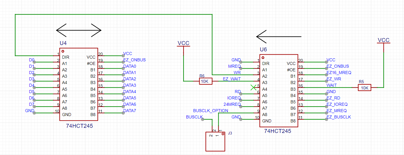
The issue I had, was not using the correct WR signal for driving the direction of the data buffer chip (U4). There are 2 signals of relevance here:
EZ_WRthe 3VWRsignal coming from the eZ80 when it is attempting to write to memory or an I/O port.WR- the buffered 5V version of this signal, coming from U6 (another 74HCT245). This is the signal sent out to the backplane for the installed modules to respond to.
As the
WRsignal is buffered, is will have a slight delay (approx 10ns) compared to the sourceEZ_WRsignal.
Previously, I had the EZ_WR signal wired to the direction input of U4, thus causing the data signals to begin to transition to inactive, before the main bus WR signal had even started to rise.
So any installed module that attempted to read the data lines, as the WR signal was going high - runs the risk of reading an invalid state.
My fix was to wire up the WR signal to the direction pin of U4. Thus ‘delaying’ when the data signals begin to transition from valid state to invalid (high impedance) state.
Although this fix implies that the data signals are going in-active (high impedance) as the
WRsignal is going high, there is a delay within the 74HCT245 as the direction signal changes – installed modules still have some time to grab their data.