eZ80 Module
eZ80 for RC2014™ and compatible backplanes
An eZ80 CPU Module that works within the RC2014™ ecosystem
31 May 2024
This is the heart of the design. A simple breakout PCB to map the various pins of the eZ80 to a standard 2.54mm (100mil) pin. Its a 4 layer PCB, (4 layer boards are very cheap these days). The 2 inner layers solid ground planes, which should help with cross talk and other noise issues.
In addition to the eZ80 chip on the PCB, there are:
- A few SMD decoupling capacitors around the chip, to help give it a nice stable 3.3V power.
- A ZDI 6 pin interface. This is the Zilog propriety interface to flash and control the chip. Using the Zilog Smart Cable adapter, I can update the flash and also do step-by-step debugging of real code on the chip.
- A 32.768kHz crystal and a couple of capacitors for the on-chip Real-Time-Clock circuit<
There has been a few iterations of this module.
The first one, I had goofed, and on one of the power lines, accidentally swapped the VDD and VSS signals - basically shorting out the power!
The 2nd iteration worked well. It included an onboard SMD oscillator (18.432Mhz) for the main clock. I tested using the Zilog Smart Cable adapter. And was able to load code on to the flash, then run it with the debugger, stepping through the instructions. Wrote some code to toggle some of the GPIO pins and confirmed that they did indeed – toggle! That was a cool moment of success!
Despite my wobbly hands and poor eyesight, this was all hand assembled successfully using my soldering iron, and a magnifier. Was very excited when it all seemed to be working as intended. (Somehow I avoided bridges across the pins of the eZ80)
For the 3rd iteration, as shown below, I removed the on-board oscillator. With the intention that the mounting PCB will provide a TTL 5V clock. This means I can use a standard DIP8 oscillator (have lots of those and much easier to solder).
I also changed the pin mounting. Before I was using standard 2.54mm PCB connectors. The same kind of connectors used on the backplane. It worked - but for this iteration, I changed to use PCB pins. They are a bit smaller – with so many pins, it will be much easier to insert and remove the module from the socket.
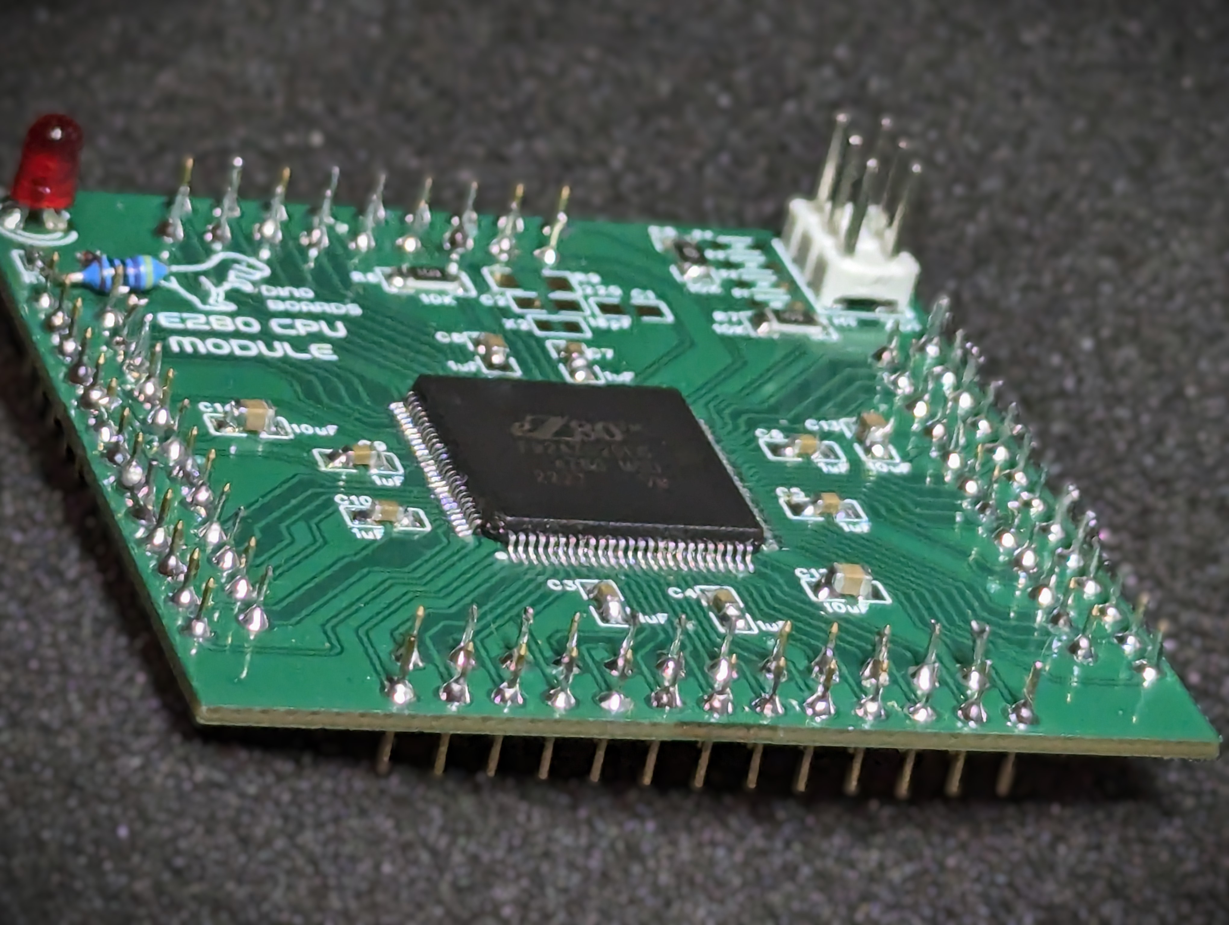
Below is a render of the a 4th design, that’s yet to be made. It has just a few minor tweaks. A fix for the LED (silkscreen has the led orientation wrong) and some other minor adjustments.
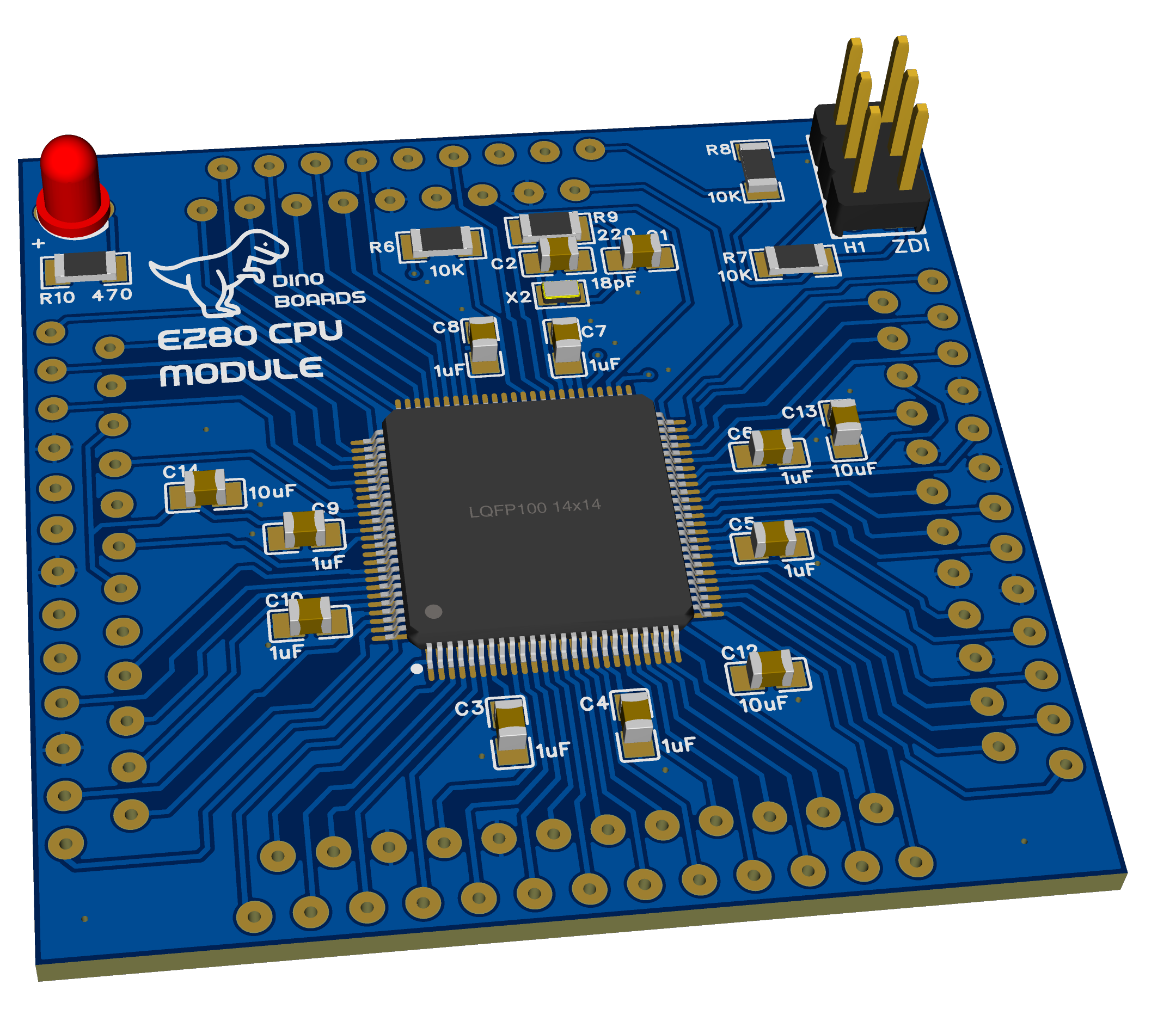
The latest schematic is under the Files sections of the Project.