Interface PCB for the backplane
eZ80 for RC2014™ and compatible backplanes
An eZ80 CPU Module that works within the RC2014™ ecosystem
31 May 2024
Next part of the design is the RC2014/RCBus compatible interface PCB.
This is a PCB that will accept the eZ80 module and also provide the buffers, clock and interface to the backplane. It must also produce the 3.3V power (stepped down from the backplane’s 5V rail).
It is also a 4 layer PCB. I had to use one of the inner layers for some of the signals - there are a lot of signals to be wired up and mapped to the main expansion pins.
It also has gone through some iterations, both as a consequence of changing the eZ80 module pin out, and also as a consequence of various design issues discovered along the way.
The key function of the PCB design is to map all the eZ80’s lines to 74HCT245 buffers. Each output line gets stepped up to 5V for the the backplane lines. And the incoming line are buffered and sent to the eZ80 module. The eZ80 module receives all input signals at 5V - utilising its ability to tolerate 5V signals. The 74HCT245 buffers will disable their output when the eZ80 is not granted access to the backplane (as described in a previous journal entry).
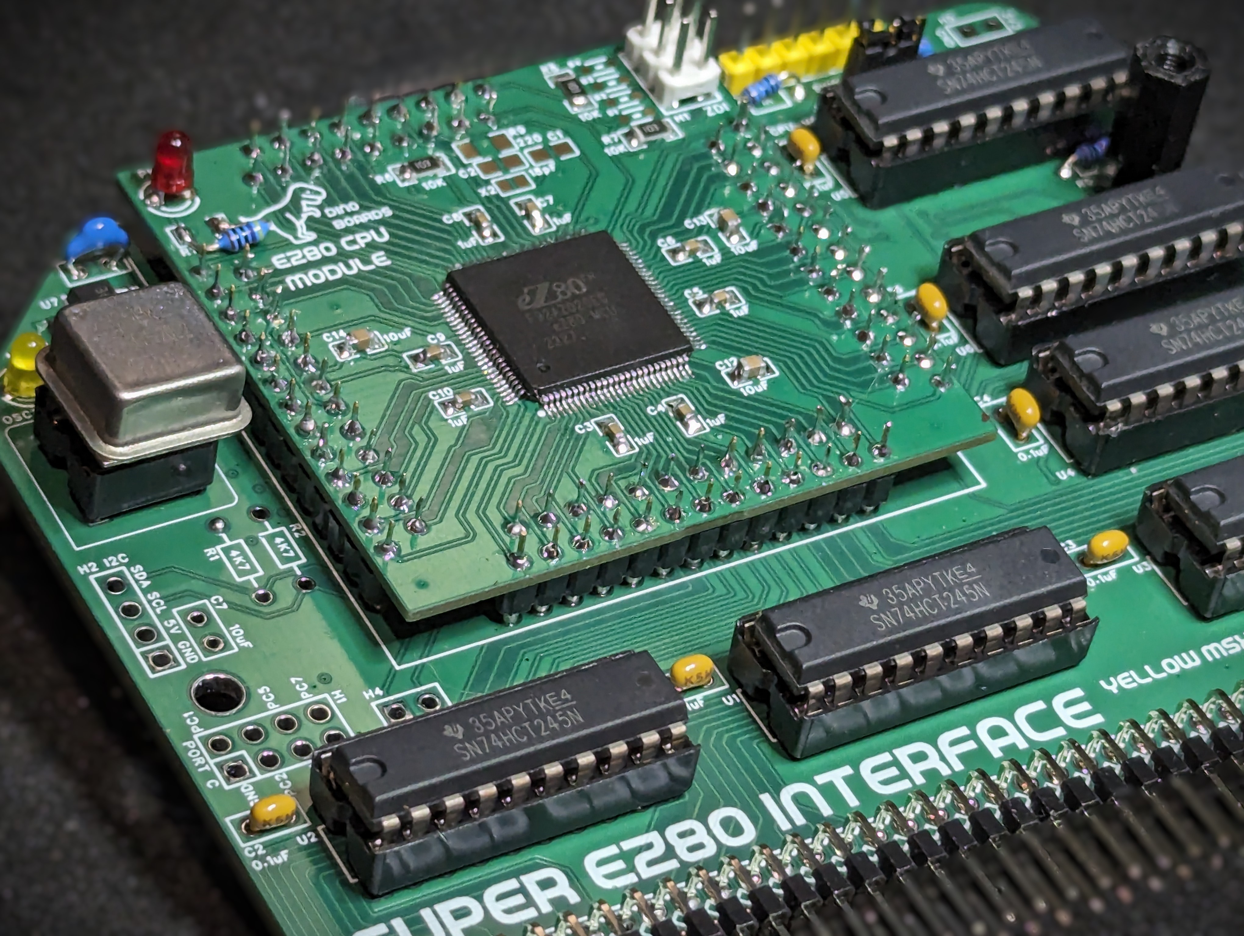
Picture below is the current ‘working’ PCB. But hidden behind the picture, are a lot of ‘corrections’. It seems I had not really understood what’s required to buffer the bi-directional data bus lines. So I had redesign this a bit. The schematic under the project’s file show the corrected solution. But I have yet to get the updated PCB for this design change. No doubt I will find other issues as this project progresses.
But even with the bodge wires and changes, the eZ80is now on my RC2014 backplane and driving the Digital IO module and reading/writing bytes to the RAM/ROM module.
I have also confirmed the UART is working by using a fairly standard RS232/USB converter. The eZ80 is sending text output over the serial connection to my PC at a mere 115200 Baud!